Tuesday, February 3, 2015

Tech Tip: How to have an N-8000AF Time Sync to NTP Server

NTP stands for Network Time Protocol, and it is an Internet protocol used to synchronize the clocks of computers to a time reference.
For this to work requires that the N-8000AF can reach the NTP Server on the Internet.
There will different ways of doing this but it is important to note the N-8000 system does require static IP addressing.  In this example, a request was made to the IT administrator to provide a range of static IP address that could get through a networks gateway to the Internet.
By using these static IP addresses the computer programming the N-8000 system and the N-8000AF would be able to reach the NTP time server.


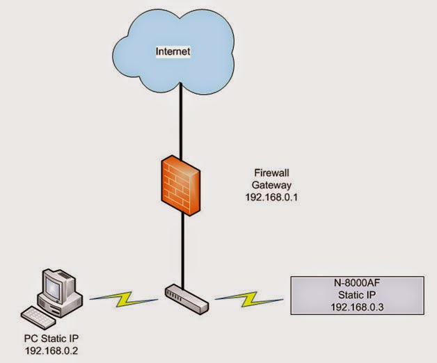
In the N-8000 Programming Software, open to the General > System Settings Tab.
Set the N-8000AF as the Clock Master and NTP Client.
In the NPT Settings enter the NTP Server address, server port and sync time in hundred hours.
If you now saved and uploaded your program file, the N-8000AF would be ready to send and receive time adjustment.

How does NTP handle the daylight savings time switchovers?


The Ability to synchronize to an NTP Time Server is now possible with the latest N-8000 Programming software ver. 4.1.0 and N-8000AF firmware ver. 4.10. This feature will keep a schools bell schedule on time year after year without ever drifting.
Because NTP is based on UTC which does not have a daylight savings time period, a switchover is not necessary inside the NTP system. The operation systems of servers and clients are solely responsible for switching from/to DST.

You will need to enable DST settings in the N-8000 to keep Bell Schedules on time in the US with only a few exceptions.
 
Trouble shooting NTP

Here is are a couple examples of when there was a successful and a not so  successful NTP time adjustment.
At 09:45:30 you see the NTP start and then 09:45:30 NTP Complete. Time adjustment was made and system is working as expected. Now see 14:30:34 and you can that there is an NTP error. Let’s explore how to troubleshoot an NTP error.

  • Check to see if the NTP server is sending a Time Adjustment back. There a number way to test an NTP server, here is a simple to use web site
In this result the NASA server at 198.123.30.132 is not sending back command “adjust time server” as it does for the UCLA server at 164.67.62.194.

NASA NTP Server
29 Jan 20:50:43 ntpdate[16444]: ntpdate 4.2.6p5@1.2349-o Mon May 20 14:24:36 UTC 2013 (1) server 198.123.30.132, stratum 0, offset 0.000000, delay 0.00000

UCLA NTP Server
29 Jan 20:52:17 ntpdate[16889]: ntpdate 4.2.6p5@1.2349-o Mon May 20 14:24:36 UTC 2013 (1) server 164.67.62.194, stratum 1, offset 0.005516, delay 0.19301
29 an 20:52:32 ntpdate[16889]: adjust time server 164.67.62.194 offset 0.005516 sec

Tech Tip: First test to see if the NTP server is sending back a time adjust. If it is and you are still getting an error proceed with these instructions.  Test the NTP Server using the same PC that is programming the N-8000 System. For example if your N-8000AF is set to 10.10.1.10 you should be able to set a PC to that same static IP address and see it get a valid return. Also disconnect the N-8000AF when doing this test so there is not an IP conflict.

  • Check the N-800AF firmware version
    • On the N-8000AF open the browser page to System Management and verify the firmware version is 4.10 or later.
NTP Server Resource
This link will provide a database of possible NTP servers worldwide.
http://support.ntp.org/bin/view/Servers/WebHome

As of this writing these two servers have been tried with success:
UCLA NTP server in UCLA (164.67.62.194)
NTP Server Port 123

Internet Multifeed (MFEED) –Japan (210.173.160.57)
NTP Server Port 123

NOTE: The NTP Server Port will always be 123 for all NTP servers.

Wednesday, August 6, 2014

Tech Tip: 25 Volt & 70V Cabling Requirements

By Jim McGuinness, Product Support Specialist

We get many calls about distributed audio and the connections associated with those systems.  Sometimes, the applications are new systems and sometimes they are replacement systems.  For new systems it might be a bit easier, since the entire system will be installed fresh and you should have control over most, if not all of the variables.  However, in a replacement system, you don’t always have control over some of the makeup of the system, namely- the wiring, in many cases.  This could be due to cable access and being able to rerun cable, or simply that replacing wiring is labor intensive and it would push the project beyond the budgetary limits set. Therefore, going with existing wiring is often the decision.  You could just have a client that doesn’t want his building knocked apart for wiring if at all possible, as he’s more interested in just replacing the head-end equipment.
 

Applications for distributed audio installations are all over the place these days.  Typical examples are schools, hospitals, nursing homes, hotels, malls, really…you name it.  When we look at these applications, we have to look at the length of cable versus the farthest distance in the system, as well as the power/current being pushed through the system.  This is a very important consideration on new or replacement systems, but especially replacement systems where cabling will be reused.  70V systems are much more forgiving with respect to cable gauge versus a 25V system.  We usually recommend 70V applications where applicable.  In some cases, it is not possible based on local code.  A couple of examples might be in hospitals or schools.  Often they are 25V systems, not 70V systems.
 

Now there’s one other factor that also has to be considered when replacing an existing system where cabling will be reused.  Was the cabling adequate for the system from the get go?  Meaning- was the proper gauge of wire used for the wattage load of the system?  This should always be checked.  What if the wattage of the system changes to a higher value?  That’s another wiring consideration.  If you are replacing a system that was originally a 25V speaker system with a 70V speaker system, then generally speaking, you should be ok.  However, going the other way around is a major concern.

Included in this article is a cable guide chart for both 25V and 70V systems.  The yellow highlighted example in the chart shows a 100 watt typical load for both a 25V and 70V system based on keeping about a 225 foot run of cable for both systems.  For a small store, this might be a pretty typical scenario.  The important point is to look at the wire gauge difference for these two systems.  For 70V you can use a relatively light, 18 gauge wire. However, for the same system in 25V, a heavy 12 gauge wire will be needed to get the same job done.  Signal loss was also considered when this chart was made, meaning that the resistance of the wire itself has to be considered as part of the added load to the amplifier.

In the second orange circled example, we looked at it a different way.  We looked at a 70V system where the impedance and wire gauge will be the constants, and using those constants to find the approximate point on the 25V system chart.  Now the distance went up a bit, but the real key here is the resulting power load limit.  Only a 15 watt system can be installed using the same gauge of wire.  In this example that’s a power factor of about 7 to 1!
 

So, it’s really important to look at these simple things to get a system to perform properly for years to come and not have any issues with the system performance.  Failed systems yield unhappy customers and we all know what that means.

Happy connecting………


Product Spotlight: TOA 5000 Series Wireless Microphone Systems

By Bob Tamburri, Marketing & Technical Support Manager
It may surprise you to learn that TOA has been manufacturing wireless microphones since 1964 (that’s way longer than most currently popular wireless mic manufacturers). We’ve even been the technology supplier for other wireless manufacturers. Needless to say, TOA has a lot of experience when it comes to wireless mics. The 5000 Series represents the latest permutation of that experience.

So, what’s so special about the 5000 Series?

First and foremost (and this is where TOAs long experience comes in) is the very robust UHF transmission & reception system employed by the 5000 Series. TOA uses 3-stage filtering  to help reduce the impact of interfering signals. These filters create a tighter “window” to allow only the desired signals through, while undesired signals are more effectively locked out.

Second, the TOA mics (both hand-held and body-pack) are designed to be extremely efficient (over 10 hrs of operation with a single AA battery) and are extremely lightweight and ergonomic (not big, heavy paperweights). We even provide an anti-roll guard on the hand-held mic body to prevent them from rolling off a table. The 5000 Series mics are also equipped with charging contacts and are compatible with the optional NiMH batteries and charging system, which eliminates the need to continually replace batteries and assures that your wireless system is always ready to perform.

Lastly, the 5000 Series squeezes lots of performance and features into a cost-competitive package. These include features not often found on similarly-priced systems such as frequency-scanning, antenna daisy-chain ports* and comprehensive LCD displays, as well as the ability to operate up to 16 simultaneous systems. And, to help cope with the ever changing UHF spectrum landscape, the 5000 Series models are available on frequencies from 576mHz to 698mHz, so you’ll always find a place to work that’s free from interference.

TOA offers a range of transmitters from hand-held (WM-5225, WM-5265 & WM-5270) to body-pack (WM-5325 with a choice of microphones) as well as Tuners (WT-5800, WT-5805 & WT-5810, plus the modular WTU-4800/WT-4820 system. Add all the necessary options (remote antennas, mics, distributors, etc…) and you’ve got a complete wireless solution that works for just about any situation. If that’s not enough, TOA protects your investment with a 5 year audio warranty (more than any other wireless manufacturer).

For more information, visit out website by clicking here.

Also, check our handy Wireless System Configuration Guide, which will help you choose the system that suits your needs by clicking here.


*WT-5800 & WT-4820 Only

Wednesday, June 4, 2014

9000M2 Preset EQs for TOA Speakers

By Jim McGuinness, Product Support Specialist

In continuing to make installation faster and better for the installer, TOA has included built-in output channel speaker EQ settings in the software that’s available for this mixer amplifier and we wanted to remind our installers of this added benefit.  There are 30+ speaker EQs to choose from for many popular models of our TOA speakers.  These EQs will make your project sound better and sound more uniform, yielding a better installation result.  This should make a happier customer and generate a better potential for a repeat customer or even new business due to positive word of mouth, or should we bring ourselves more up to date like word of Twitter, Facebook, Instagram, etc.  Dare I say e-mail?

So old school!

Implementing EQ settings is very easy.  First open your software project so that you get the main screen as shown below.  Then click on the Blue EQ button of the channel you want to equalize.  The EQ page will display at the bottom of the screen.
Remember for EQ settings, you will have to click on the EQ button for each channel you want to equalize.  This is different from the other output settings which will display all channels at the bottom of the screen.  This I primarily due to EQ information takes up too much space to be able to display all EQ channels at the same time.

Next, click on the dropdown menu option that by default says “ALL FLAT.”

You will see the list of speaker options to choose from as shown below.
Once you click on the speaker option needed, the EQ curve(s) will be available for review on the lower part of the screen.  The HX-5 speaker is listed in this example.  If you would like to review the EQ frequency points, click on the dropdown for the Select (1-12).  There you will have up to twelve points that can be reviewed if available.  Some speakers may only have 1 or 2 points where other speakers might have 7 or 8 points.  In the case of the HX-5, there are 5 points that you can review.  As you review EQ points, when the next point number to be reviewed lists “Through,” then there are no more points for that speaker.
Now for an additional programming trick.  If you have multiple channels with the same speaker, you can copy paste from one channel to another.  Here are the simple steps for this.

First set the EQ curve desired on the lower part of the screen as previously described above on a channel to be equalized.  In this example Channel 1 was chosen.  Once selected, right button click
 your mouse on the CH1 box
on the top part of your screen and select Copy.


Then right button click on the target channel box you want to copy the EQ curve to and click paste.  In this example channel 2
was chosen.  That’s it.  You will be able to confirm the curve on the bottom of the screen.


Now some final notes regarding Preset EQs.

Preset EQs can only be initially set from the programming software, not by the front panel controls of the mixer amplifier.  Once set and loaded to the mixer amplifier, Preset EQs can be turned on and off via the front panel.

Preset EQs can only be reviewed, not changed.  If you need to change a point in a Preset EQ for your installation application, you will need to review the EQ points as described above and write down the parameters for each point.  Then you can modify the EQ curve as necessary by creating your own EQ curve from the software or the front panel controls.

Importantly remember to save your scene for the EQ settings you have made.  Don’t for get to save the project to your computer as well for backup.  Lastly click on Communication and select Upload PC to 9000 > All Data, to get your changes in the amplifier mixer.

Happy sound shaping……

Wednesday, April 2, 2014

ZM-901x Remote Buttons as Volume Controls

By James McGuinness, Product Support Specialist

We get lots of questions regarding the various uses for the serial RS-485 ZM-9011, ZM-9012, ZM-9013 and ZM-9014 remotes.  One popular one is about volume control.  Now the ZM-9012 (rotary volume only) and the ZM-9014 have a dedicated rotary volume control and it can be assigned to be an input channel volume control, an output channel volume control, a grouped input channel volume control or a grouped output channel volume control.  But did you know that you can make the buttons on so equipped serial remotes into volume controls similar to the functionality of a ZM-9001 or ZM-9002 wired remote control?  The only requirement is that you have available pairs of contact inputs and outputs available for this application.

So for this example let’s use an A-9060SM2 where we are going to have two inputs with button volume controls and a master output volume control using a ZM-9014 serial remote control.  Of course to complete the basic equipment list you will need an input module such as the D-001T, an RC-001T serial remote control module, and its power supply the AD-246.

For connections we will not go over the basic input and output connections, and the basic RC-001T connections which you should know by now.  Of course if you need a reminder, examples are available in the instruction manual.  However, let’s look at the connections required for this application as they apply to the 14 pin control connector.


 Standard Control Port Available On All 9000M2 Mixers Shown Above

We are going to marry two sub-systems together, the RS-485 serial remotes along with our contact closure circuits.  To start to make this application work, we need to connect 4 input contact closures to 4 output contact closures.  The reason for this is we can control the output contact closures with the serial remotes and operate them via the buttons on the remote, and we can set the input contact closures for volume control use.  Can you see where we’re going with this?

In the picture below you will see the physical connections necessary to make this work.  It’s simple, connect input 1 to output 1 and so on.  A ground or “E” connection is not necessary as we are not connecting off the mixer itself, so internal ground will take care of it.


Now you have all the connections necessary to make this work, so let’s take a look at the programming screens to finish the control.

First we want to go to Setting and then C-IN Setting…


On the next page you will see the options available for the C-IN control.  In our example we choose volume up and down twice as shown under Parameter and the input sources are married to a pair of volume up and down contacts using the Channel/Scene dropdowns.  You then can choose the resolution of the button presses between 0.5dB ~ 10dB in their respective dropdowns.  We have chosen 1dB in this example.


Once this is all done click OK and the screen will save and close.  Now we will move on to the serial remote settings.

First go to Setting and then Remote Setting Wizard…


On the next screen you will see the remote settings page for 2-wire remote controls which are the
ZM-9001 & ZM-9002 which we are not using.  Select None for both Remote Volume 1 & 2 and click Next.


Then we will get the serial remote start page.


On the initial serial remote setup page above, select 1 remote, Simultaneous Mode, and the ZM-9014 remote options.  The ZM-9014 comes set from the factory at address 0 so you won’t need to change this typically.  However, please check that the software setting for address matches the remote’s setting.  Normally you will start at address 0.  Now the reason why we chose Simultaneous Mode for this exercise is let’s say this is for a conference area.  The mic may need to be on at the same time as the BGM music or audio source.  This setting will allow that.  If set to Exclusive mode, you will only be able to choose one input at a time and pressing the volume keys may in some cases affect your input source.  Okay, now click Next.


Now you see the programming screen of the ZM-9014 above.  From the Function Select dropdown menus you will select Change C-OUT for all 4 buttons.  Under Assigned Value you have 2 options, Level and Toggle.  This is somewhat confusing.  I would rather have the terms Pulse for Level and Latch for Toggle.  So for our application we want to choose Level “Pulse” for all four dropdowns.  To the right of this option you have dropdowns which are unlabeled.  These dropdowns are the contact control output settings.  Set the options as shown 1 ~ 4 as we have used buttons 1 ~ 4 in order and that’s how we wired the contact inputs and outputs earlier in our discussion.  Lastly for the rotary volume control, select Output Volume and the Assigned output channel 01.  Then click Finish.

Now you’re all set.  Your ZM-9014 will work completely like a volume control.  The upper two buttons will be the volume control for the Mic and the bottom two buttons will be the volume control for the BGM or audio input.  The rotary volume control will be the master output volume control.
TIP:  Now if you want to have more than one of these remotes in the room, no problem.  You can add more ZM-9014 volume controls around the room, just program them similarly as the first remote.  You will just have different address settings for each on the initial serial remote settings page.  The neat thing is that each volume control knows what the other one is doing so the volume display on each volume control will be the same around the room.  No wondering what one volume control is doing versus another one.

Happy programming………remotely speaking.